Q. No 16: Explain the underlying principle and working of an electric generator by drawing a labelled diagram. What is the function of brushes? Ans: An electric generator converts mechanical energy into electrical energy. The principle behind the electric motor is based on Fleming’s right hand rule.
when a coil of insulated copper wire is forced to rotate inside a magnetic field then electric current is induced. The following figure shows circuit diagram of a simple AC generator. If axle X is rotated clockwise, then the length PQ moves upwards and the length RS moves downwards.
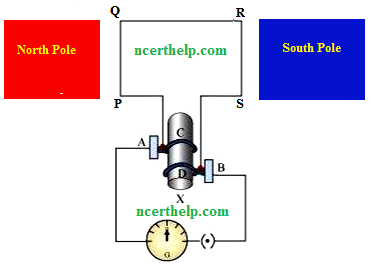
Since the lengths PQ and RS are moving in a magnetic field, a current will be induced due to electromagnetic induction. Length PQ is moving upwards and the magnetic field acts from left to right. Hence, according to Fleming’s right hand rule, the direction of induced current will be from P to Q. Similarly, the direction of induced current in the length RS will be from R to S. The direction of current in the coil is PQRS. Hence, the galvanometer shows a deflection in a particular direction. After half a rotation, length PQ starts moving down whereas length RS starts moving upward. The direction of the induced current in the coil gets reversed as SRQP. As the direction of current gets reversed after each half rotation, the produced current is called an alternating current (AC). To get a unidirectional current, instead of two slip rings, two split rings are used, as shown in the following figure. In this arrangement, brush A always remains in contact with the length of the coil that is moving up whereas brush B always remains in contact with the length that is moving down. The split rings C and D act as a commutator.
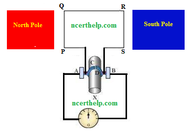
The direction of current induced in the coil will be PQRS for the first half and SRQP in the second half of the rotation. Therefore a unidirectional current is produced from the generator called DC generator


